
 Made in Salisbury, MD USA |
Custom Transformers
Let us design a transformer that fits your needs!
Specify NowStandard Transformer
View our Standard Design Toroidal Transformers.
View Now
FAQs
A transformer is a static piece of apparatus with two or more windings which, by electromagnetic induction, transforms a system of alternating voltage and current into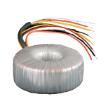 another system of voltage and current of same values or of different values, and at the same frequency for the purpose of transferring electrical power.
Although transformers look simple, its design involves a few very important electromagnetic laws and formulas, which were developed by Joseph Henry and Michael Faraday.
As mentioned above, one of the important building blocks is a two-coil wire - namely primary and secondary windings. These two windings are placed in a very close proximity and are linked by the alternate flux in the core. As the result, the voltage is induced in the winding. The formula below is used to calculate the induced voltage in the secondary winding.
E = kAcNBmf(10-4)
Where,
E – induced voltage
k – constant, 4.44 for sinewave
4.00 for squarewave
Ac – cross section area of core in cm2
N – number of turn which induces the voltage
Bm – maximum flux density of the core in Tasla
f – frequency in Hz
Armed with the above formula, one can increase or decrease the amount of turns of the winding to increase or decrease the induced voltage. Indeed, there are more turns on the secondary winding than in the primary winding for a step-up transformer and vise versa for a step-down transformer.
As many wonder what a transformer may do, if the windings are not correctly designed and manufactured, they may cause harm to the system in which the transformer is used, and put the user in danger because of the risk of electrocution, burns, and fires. At Toroid Corporation, we take pride in the design and fabrication of our toroidal transformers. We design the transformers to be accurate to the customers’ specifications and make them safe, highly efficient and long-lasting.
We don't have distributors, but we have knowledgeable sales reps located throughout the country who can help you find what you need, or you can order direct from our factory.
Leads on our standard transformers generally run 8" long. If your application requires something different, contact the factory directly for our custom lead lengths.
We have found that most design engineers are not aware of the subtle nuances they receive with their toroidal transformer. By soldering on a (heavy) insulated wire to a secondary and adding turns on top of the Mylar Insulation, you can increase the voltage of the prototype. Conversely, you can decrease the voltage of the transformer by reversing the direction of the turns. This allows you to perform very simple fine-tuning of your prototype without having to order a completely new one.
Step 1: Determine which winding you want to adjust the output voltage on.
Step 2: Splice/Solder on additional wire to one of the leads of that winding.
Step 3: Put the lead(s) through the center hole and bring it back to the original point. If the direction of the winding is in the same direction of original winding, it adds one turn on the transformer. If the winding direction is opposite to the direction of original winding, you subtract one turn. To add on or take off more turns, just repeat the process more times.
Step 4: It is important to measure the voltage after the first turn so you can see how much voltage you are adding or subtracting from your lead. Measuring your voltage after the first turn will also give you a better idea of exactly how many turns you will need to reach your desired voltage.
Here are some guidelines for how many turns you may need for 60Hz transformers:
| Transformer size | Volts/turn |
|---|---|
| 30 VA 120 VA 500 VA 1000 VA | 0.08 0.15 0.35 0.585 |